
")


- Posts: 51
- Thank you received: 42
Die Bosch D-Jetronic war 1967 die erste Großserien elektronische Einspritzung der Welt. - Bosch's D-Jetronic was the first mass-production electronic fuel injection.
350 SLC 1972 troubleshooting
- dispoman
- Topic Author
- Offline
- Senior Member
-

Less
More
25 May 2018 13:14 - 25 May 2018 13:17 #9389
by dispoman
350 SLC 1972 troubleshooting was created by dispoman
Hello,
Last year I bought an Mercedes 350 SLC to make an historic racing car.
The car was not running very well but it was starting quite ok cold or hot.
Clearly not all 8 cylinders were working.
It has a manual 4 speed gearbox and minimum rust on the body (I've seen most of the manual car available in Europe at this time, and some were really rusted).
I did a cylinder compression test, all 8 were ok.
I did a plug spark check on all 8 cylinders, i was ok.
Clearly there was a problem with the injection system.
I bought the car in Netherlands and bring it back to Paris on a trailer.
The car was sold new in Germany in 72 and came in the Netherlands in 99.
Last edit: 25 May 2018 13:17 by dispoman.
The following user(s) said Thank You: thomasgu
Please Log in or Create an account to join the conversation.
- dispoman
- Topic Author
- Offline
- Senior Member
-
Less
More
- Posts: 51
- Thank you received: 42
25 May 2018 13:26 #9390
by dispoman
Replied by dispoman on topic 350 SLC 1972 troubleshooting
At first i took care of the rust.
Then stripping the interior, adding a rollcage, installing race shock and springs, racing brake hoses, race seats, rally radio and some other FIA compliant items.
With the car came some spare parts and another ECU in the trunk.
The car was starting fine either cold or hot.
The idle was rough but stable.
It seems to be working better at higher revs.
I did try the other ECU and the car was running very badly with some black smoke.
I put back the original ECU back in the car.
Two weeks ago after adding a voltmeter on the dashboard i try to start again the car And the idle was not stable anymore and the car not reving.
I really needed to get deep into the website and start to troubleshoot the engine.
The following user(s) said Thank You: thomasgu
Please Log in or Create an account to join the conversation.
- dispoman
- Topic Author
- Offline
- Senior Member
-
Less
More
- Posts: 51
- Thank you received: 42
25 May 2018 13:36 #9391
by dispoman
Replied by dispoman on topic 350 SLC 1972 troubleshooting
First I tried again the spare ECU, the car was running as badly as before with it but at least it stared.
Then I tested the 25 pin ECU connector with my multimeter.
The air sensor was ok,
Injector group value were high on group 1 and 4 around 3 ohms
Map sensor values were ok
Throttle switch is ok
Ground and power supply are OK
Fuel relai is OK
Trigger contact are of limits
Water sensor is OK
Then I tested the 25 pin ECU connector with my multimeter.
This image is hidden for guests.
Please log in or register to see it.
Please log in or register to see it.
The air sensor was ok,
Injector group value were high on group 1 and 4 around 3 ohms
Map sensor values were ok
Throttle switch is ok
Ground and power supply are OK
Fuel relai is OK
Trigger contact are of limits
Water sensor is OK
The following user(s) said Thank You: thomasgu
Please Log in or Create an account to join the conversation.
- dispoman
- Topic Author
- Offline
- Senior Member
-
Less
More
- Posts: 51
- Thank you received: 42
25 May 2018 13:40 - 25 May 2018 13:41 #9392
by dispoman
Replied by dispoman on topic 350 SLC 1972 troubleshooting
I have check the injectors to see which one were not working.
With the car history, I had an invoice for the injector cleaning few years ago.
So I started with the wires, they were OK.
The injector resistance is OK around 1.2 ohm with a direct test.
The problem was from the plugs.
I renew the connections and now it is fine.
With the car history, I had an invoice for the injector cleaning few years ago.
So I started with the wires, they were OK.
The injector resistance is OK around 1.2 ohm with a direct test.
The problem was from the plugs.
I renew the connections and now it is fine.
Last edit: 25 May 2018 13:41 by dispoman.
The following user(s) said Thank You: thomasgu
Please Log in or Create an account to join the conversation.
- dispoman
- Topic Author
- Offline
- Senior Member
-
Less
More
- Posts: 51
- Thank you received: 42
25 May 2018 13:52 - 25 May 2018 13:54 #9393
by dispoman
Replied by dispoman on topic 350 SLC 1972 troubleshooting
I then try to find a way to test the trigger contacts.
I added some wires on the TC connector on the distributor ( which by the way is 0231402008 ant not 009) in order to check the dwell angle with my multimeter.
I then start the engine and did the following test.
TC4 then TC1 then TC2 then TC3
The contacts seems to be off wear limits and the TC3 really wrong with 344°.
I added some wires on the TC connector on the distributor ( which by the way is 0231402008 ant not 009) in order to check the dwell angle with my multimeter.
This image is hidden for guests.
Please log in or register to see it.
Please log in or register to see it.
I then start the engine and did the following test.
TC4 then TC1 then TC2 then TC3
The contacts seems to be off wear limits and the TC3 really wrong with 344°.
Last edit: 25 May 2018 13:54 by dispoman.
The following user(s) said Thank You: thomasgu
Please Log in or Create an account to join the conversation.
- dispoman
- Topic Author
- Offline
- Senior Member
-
Less
More
- Posts: 51
- Thank you received: 42
25 May 2018 14:02 #9394
by dispoman
Replied by dispoman on topic 350 SLC 1972 troubleshooting
I then remove the distributor to check the trigger contacts.
First I did a simple test to check the contacts with some masking tape and a 4 colors pen.
All seems ok not compliant with the dwell test above on TC3
First I did a simple test to check the contacts with some masking tape and a 4 colors pen.
All seems ok not compliant with the dwell test above on TC3
This image is hidden for guests.
Please log in or register to see it.
Please log in or register to see it.
The following user(s) said Thank You: thomasgu
Please Log in or Create an account to join the conversation.
- dispoman
- Topic Author
- Offline
- Senior Member
-
Less
More
- Posts: 51
- Thank you received: 42
25 May 2018 14:11 - 25 May 2018 17:07 #9395
by dispoman
Replied by dispoman on topic 350 SLC 1972 troubleshooting
I open the trigger contact to find this ...
Do you think it might be a problem ?
The broken parts seems to center the trigger contacts, may be it is why I got a bad value on tc 3.
The contacts points cams are around 2mm, probably why I have found around 180° dwell angle. I need to adjust Them.
I have check the Mercedes EPC for a replacement part.
The only reference part are 000 158 01 19 or 03 19 but it is for the contact itself, not the TC cover.
Do you know if this part is still available ?
The cams seems OK.
This image is hidden for guests.
Please log in or register to see it.
Please log in or register to see it.
Do you think it might be a problem ?
The broken parts seems to center the trigger contacts, may be it is why I got a bad value on tc 3.
The contacts points cams are around 2mm, probably why I have found around 180° dwell angle. I need to adjust Them.
This image is hidden for guests.
Please log in or register to see it.
Please log in or register to see it.
This image is hidden for guests.
Please log in or register to see it.
Please log in or register to see it.
I have check the Mercedes EPC for a replacement part.
The only reference part are 000 158 01 19 or 03 19 but it is for the contact itself, not the TC cover.
Do you know if this part is still available ?
The cams seems OK.
Last edit: 25 May 2018 17:07 by dispoman.
The following user(s) said Thank You: thomasgu
Please Log in or Create an account to join the conversation.
- Dr-DJet
-

- Offline
- Moderator
-

- Dr-DJet repariert und sammelt alles! :-)
25 May 2018 18:18 #9399
by Dr-DJet
Viele Schraubergrüße - best regards, Dr-DJet Volker
Alles für den Mercedes-Benz R/C 107 und W116 in der SLpedia Sternzeit 107
Workshops Hzg/Klima 16.5.(ER), D-Jet 20.6.(ER)/29.8.(F), KA-Jet 30.5.(HU), KE-Jet 11.7.(ER)
This image is hidden for guests.
Replied by Dr-DJet on topic 350 SLC 1972 troubleshooting
Hi Sylvain,
yes this plate slides into the shaft of the distributor and centers it around that shaft. When one edge is missing it could start to move and cause such problems. I have seen similiar effects before when I run D-Jetronic ignition distributors in my test stand. Looked fine in static test and with measuring gauge. but then on test stand it did not! Reason was 2 loose screws of foxbravo (or his ignition distributor). I have heard of other problems where rivets of the plate under the contacts were loose.
Everything must be fixed and well centered! Otherwise Trigger contacts wander around in ignition distributor.
Viele Schraubergrüße - best regards, Dr-DJet Volker
Alles für den Mercedes-Benz R/C 107 und W116 in der SLpedia Sternzeit 107
Workshops Hzg/Klima 16.5.(ER), D-Jet 20.6.(ER)/29.8.(F), KA-Jet 30.5.(HU), KE-Jet 11.7.(ER)
This image is hidden for guests.
Please log in or register to see it.
The following user(s) said Thank You: thomasgu
Please Log in or Create an account to join the conversation.
- nordfisch
-
- Offline
- Platinum Member
-

Less
More
- Posts: 2798
- Thank you received: 790
25 May 2018 18:31 - 25 May 2018 18:59 #9400
by nordfisch
Replied by nordfisch on topic 350 SLC 1972 troubleshooting
Hi Sylvain
and Welcome at jetronic.org
The part that is broken away is meant for centering the trigger points set as you mentioned before.
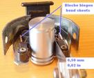
In my opinion you have to buy a replacement or you have to reconstruct the missing side.
You need a reliable and loadable function...
It should be possible to reconstruct the part using a 2,0 mm sheet metal.
The problem is the original material is zinc cast metal. You can't weld it, but perhaps solder it (maybe using a brass replacement??.
I managed to solder zinc cast metal in the past.
Or you could use the two holes to fix the spare.
The distance between the two sides has to be 18,5 mm.
I developed a tool for adjusting the points. I could send you a figure for producing it on a lathe for free.
Contact me via PM if you want the figure.
I also have a used trigger-set in good condition to sell.
Regards
Norbert
and Welcome at jetronic.org
The part that is broken away is meant for centering the trigger points set as you mentioned before.
In my opinion you have to buy a replacement or you have to reconstruct the missing side.
You need a reliable and loadable function...
It should be possible to reconstruct the part using a 2,0 mm sheet metal.
The problem is the original material is zinc cast metal. You can't weld it, but perhaps solder it (maybe using a brass replacement??.
I managed to solder zinc cast metal in the past.
Or you could use the two holes to fix the spare.
The distance between the two sides has to be 18,5 mm.
I developed a tool for adjusting the points. I could send you a figure for producing it on a lathe for free.
Contact me via PM if you want the figure.
I also have a used trigger-set in good condition to sell.
Regards
Norbert
Last edit: 25 May 2018 18:59 by nordfisch. Reason: changed ideas for a repair
The following user(s) said Thank You: thomasgu
Please Log in or Create an account to join the conversation.
- dispoman
- Topic Author
- Offline
- Senior Member
-
Less
More
- Posts: 51
- Thank you received: 42
25 May 2018 20:47 #9404
by dispoman
Replied by dispoman on topic 350 SLC 1972 troubleshooting
Thank you for your answers.
I will need to find a new or used part i guess.
If the distance between the two sides needs to be 18.5mm , i am far from it ...
I will need to find a new or used part i guess.
If the distance between the two sides needs to be 18.5mm , i am far from it ...
This image is hidden for guests.
Please log in or register to see it.
Please log in or register to see it.
The following user(s) said Thank You: thomasgu
Please Log in or Create an account to join the conversation.
- nordfisch
-
- Offline
- Platinum Member
-
Less
More
- Posts: 2798
- Thank you received: 790
25 May 2018 21:20 #9405
by nordfisch
Replied by nordfisch on topic 350 SLC 1972 troubleshooting
No, you misunderstood...
Distance between rubber blocks has to be about 23,0 mm.
Distance between the missing part and the other side has to be 18,5 mm
regards
Norbert
Distance between rubber blocks has to be about 23,0 mm.
Distance between the missing part and the other side has to be 18,5 mm
regards
Norbert
The following user(s) said Thank You: thomasgu
Please Log in or Create an account to join the conversation.
- dispoman
- Topic Author
- Offline
- Senior Member
-
Less
More
- Posts: 51
- Thank you received: 42
26 May 2018 10:00 #9410
by dispoman
Replied by dispoman on topic 350 SLC 1972 troubleshooting
OK
The following user(s) said Thank You: thomasgu
Please Log in or Create an account to join the conversation.
- Dr-DJet
-
- Offline
- Moderator
-
- Dr-DJet repariert und sammelt alles! :-)
26 May 2018 11:18 #9414
by Dr-DJet
Viele Schraubergrüße - best regards, Dr-DJet Volker
Alles für den Mercedes-Benz R/C 107 und W116 in der SLpedia Sternzeit 107
Workshops Hzg/Klima 16.5.(ER), D-Jet 20.6.(ER)/29.8.(F), KA-Jet 30.5.(HU), KE-Jet 11.7.(ER)
This image is hidden for guests.
Replied by Dr-DJet on topic 350 SLC 1972 troubleshooting
Hi,
rubber blcoks meaning Pertinax cams ?
rubber blcoks meaning Pertinax cams ?
Viele Schraubergrüße - best regards, Dr-DJet Volker
Alles für den Mercedes-Benz R/C 107 und W116 in der SLpedia Sternzeit 107
Workshops Hzg/Klima 16.5.(ER), D-Jet 20.6.(ER)/29.8.(F), KA-Jet 30.5.(HU), KE-Jet 11.7.(ER)
This image is hidden for guests.
Please log in or register to see it.
The following user(s) said Thank You: thomasgu
Please Log in or Create an account to join the conversation.
- nordfisch
-
- Offline
- Platinum Member
-
Less
More
- Posts: 2798
- Thank you received: 790
26 May 2018 16:31 #9419
by nordfisch
Yes, I don't know the correct idiom - called them so in my tool's instruction.
Regards
Norbert
Replied by nordfisch on topic 350 SLC 1972 troubleshooting
Volker wrote: Hi,
rubber blcoks meaning Pertinax cams ?
Yes, I don't know the correct idiom - called them so in my tool's instruction.
Regards
Norbert
The following user(s) said Thank You: thomasgu
Please Log in or Create an account to join the conversation.
- dispoman
- Topic Author
- Offline
- Senior Member
-
Less
More
- Posts: 51
- Thank you received: 42
29 May 2018 20:36 - 29 May 2018 20:43 #9431
by dispoman
Replied by dispoman on topic 350 SLC 1972 troubleshooting
As i am waiting to receive my new trigger contacts, i decided to test the fuel pressure.
I have orderd a fuel pressure gage on ebay. .
Received it today and conduct a first test.
I added the gage on the incoming fuel line just before the injector common rail.
I put the switch key on, listen for the fuel pump for 2 seconds and see the gage climbing to 1.9 bars.
When i start the engine, the gage is set to a full 2 bars as you can see on the following video (it wasn't my first try that is why the gage is not a zero at the beginning).
30 minutes after a test, the fuel pressure is getting down. I am note sure if this is normal.
As soon as the key switch is on again the ful pump is on for 2 seconds and it goes back to 1.9.
I guess this overall behavior is normal. And i consider the fuel supply system to be working fine.
I have orderd a fuel pressure gage on ebay. .
Received it today and conduct a first test.
I added the gage on the incoming fuel line just before the injector common rail.
This image is hidden for guests.
Please log in or register to see it.
Please log in or register to see it.
I put the switch key on, listen for the fuel pump for 2 seconds and see the gage climbing to 1.9 bars.
This image is hidden for guests.
Please log in or register to see it.
Please log in or register to see it.
When i start the engine, the gage is set to a full 2 bars as you can see on the following video (it wasn't my first try that is why the gage is not a zero at the beginning).
30 minutes after a test, the fuel pressure is getting down. I am note sure if this is normal.
This image is hidden for guests.
Please log in or register to see it.
Please log in or register to see it.
As soon as the key switch is on again the ful pump is on for 2 seconds and it goes back to 1.9.
I guess this overall behavior is normal. And i consider the fuel supply system to be working fine.
Last edit: 29 May 2018 20:43 by dispoman.
The following user(s) said Thank You: thomasgu
Please Log in or Create an account to join the conversation.
- nordfisch
-
- Offline
- Platinum Member
-
Less
More
- Posts: 2798
- Thank you received: 790
29 May 2018 21:29 #9433
by nordfisch
Replied by nordfisch on topic 350 SLC 1972 troubleshooting
Hi Sylvain,
the behavior is o.k.
Pressure is allowed to sink to 1,8 Bar - and has to hold then for a minute or so.
Please check your measuring device. We found out the manometers are misadjusted quite often.
Cross-check it with a reliable unit - maybe a tyre-manometer professionally used at a gas station.
Regards
Norbert
The following user(s) said Thank You: thomasgu
Please Log in or Create an account to join the conversation.
- dispoman
- Topic Author
- Offline
- Senior Member
-
Less
More
- Posts: 51
- Thank you received: 42
30 May 2018 15:50 #9436
by dispoman
Replied by dispoman on topic 350 SLC 1972 troubleshooting
I will try to benchmark my pressure gage.
The following user(s) said Thank You: thomasgu
Please Log in or Create an account to join the conversation.
- dispoman
- Topic Author
- Offline
- Senior Member
-
Less
More
- Posts: 51
- Thank you received: 42
30 May 2018 15:58 #9437
by dispoman
Replied by dispoman on topic 350 SLC 1972 troubleshooting
To continue my troubleshooting, I opened my ECU to try to see if there is something obviously wrong with it.
It is a 0 280 002 004 that is correct for the 350 SLC engine.
It has an RT sticker and mark on it.
Not sure what RT stand for.
There is also a j118 and j101 marking inside.
There is some blue marks on the components.
It seems to have been previously tested or repaired.
Is there some simple way to test if with a multimeter or should I have an oscilloscope ?
Regards
Sylvain
It is a 0 280 002 004 that is correct for the 350 SLC engine.
It has an RT sticker and mark on it.
Not sure what RT stand for.
This image is hidden for guests.
Please log in or register to see it.
Please log in or register to see it.
This image is hidden for guests.
Please log in or register to see it.
Please log in or register to see it.
There is also a j118 and j101 marking inside.
This image is hidden for guests.
Please log in or register to see it.
Please log in or register to see it.
There is some blue marks on the components.
It seems to have been previously tested or repaired.
This image is hidden for guests.
Please log in or register to see it.
Please log in or register to see it.
This image is hidden for guests.
Please log in or register to see it.
Please log in or register to see it.
Is there some simple way to test if with a multimeter or should I have an oscilloscope ?
Regards
Sylvain
The following user(s) said Thank You: thomasgu
Please Log in or Create an account to join the conversation.
- nordfisch
-
- Offline
- Platinum Member
-
Less
More
- Posts: 2798
- Thank you received: 790
30 May 2018 16:35 #9438
by nordfisch
Replied by nordfisch on topic 350 SLC 1972 troubleshooting
Hi Sylvain,
RT means: produced in Reutlingen
228 means: produced 8/1972
I can't see any signs of a former repair. These ECUs were made by hand and tuned by hand to values only Bosch knew and very few others nowadays..
You can't check it with a multimeter. Maybe you could test some basic functions - but an oscilloscope wouldn't help you, too.
This is work for specialists. But some of them saying they could do the job don't have the specific references needed for a complete check.
Take care of them - it's not worth a try. They will mostly find something to repair... and you can get it back in worse condition than you sent it in.
This is an analog device - not a digital one. Changing one value mostly effects others.
Look at the marked resistors. They have ECU-specific values for the tuning, mostly different from ECU to ECU of the same type and number.
Regards
Norbert
The following user(s) said Thank You: thomasgu
Please Log in or Create an account to join the conversation.
- dispoman
- Topic Author
- Offline
- Senior Member
-
Less
More
- Posts: 51
- Thank you received: 42
30 May 2018 19:51 #9439
by dispoman
Replied by dispoman on topic 350 SLC 1972 troubleshooting
thanks for the information.
As i understand the blue marks are made at the factory in 72, correct ?
As i understand the blue marks are made at the factory in 72, correct ?
The following user(s) said Thank You: thomasgu
Please Log in or Create an account to join the conversation.
Time to create page: 0.156 seconds